This product is not available for new orders. We recommend ordering: CR1000Xe.
| Services Available | |
|---|---|
| Repair | Yes |
| Calibration | Yes |
Visão Geral
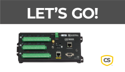
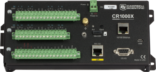
O CR1000X é o nosso principal registrador de dados que fornece medição e controle para uma ampla variedade de aplicações. Sua confiabilidade e robustez fazem dele uma excelente opção para aplicações remotas em ambientes hostis, incluindo estações meteorológicas, sistemas remotos, perfilhamento do vento, aplicações geotécnicas, monitoramento da qualidade do ar, sistemas hidrológicos, monitoramento da qualidade da água e estações hidrometeorológicas.
O CR1000X é um dispositivo de baixo consumo que mede sensores, com possibilidade de comunicação direta e telemetria, análise e processamento de dados, controle de dispositivos externos e armazenamento interno de dados. A placa principal é protegida por uma caixa selada de aço inoxidável contra interferências de RF. O relógio interno é mantido por bateria que garante a precisão. A linguagem de programação embarcada, do tipo BASIC, comum a todos os registradores de dados da Campbell Scientific, suporta rotinas de coleta, processamento, análise de dados e controle.
Leia maisBenefícios e Características
- Operacional em ambientes extremos com faixa de operação padrão de -40 ° a + 70 °C ou faixa estendida de -55°C a + 85°C
- Conexão direta com à porta USB do computador
- Alta sensibilidade a variação de medidas analógicas a uma taxa de 300+ Hz
- Diferenciação de pequenas alterações nos valores dos dados com alta resolução (A/D 24 bits)
- Inclui dois canais de entrada de corrente não isolados para sensores de corrente de 0 a 20 mA ou 4 a 20 mA saídas
- Contém uma porta CPI integrada para hospedar sensores de alta velocidade Campbell e módulos externos (CDM)
- Conecta-se diretamente à Ethernet
- Entrada para cartão microSD para expansão da memória e requisitos
- Fornece integração e medição de sensores seriais com SDI-12, RS-232 e /ou RS-485
- Suporte completo para rede PakBus
- Inclui página da web incorporada para conexão direta via navegador de rede
imagens


3D / CAD Files:
Descrição Técnica
O CR1000X é um dispositivo de baixo consumo que mede sensores, com possibilidade de comunicação direta e telemetria, análise e processamento de dados, controle de dispositivos externos e armazenamento interno de dados. A placa principal é protegida por uma caixa selada de aço inoxidável contra interferências de RF. O relógio interno é mantido por bateria que garante a precisão. A linguagem de programação embarcada, do tipo BASIC, comum a todos os registradores de dados da Campbell Scientific, suporta rotinas de coleta, processamento, análise de dados e controle.
O painel de conexões do CR1000X inclui duas portas 12 V chaveadas, 16 portas analógicos, blocos de terminais desconectáveis facilitando a rápida manutenção.
Compatibilidade
Please note: The following shows notable compatibility information. It is not a comprehensive list of all compatible products.
Measurement and Control
| Product | Compatible | Note |
|---|---|---|
| SDM-SIO2R |
Software
| Product | Compatible | Note |
|---|---|---|
| DevConfig | Version 2.16 or higher | |
| KonectGDS | ||
| LoggerLink | Version 1.6 or higher | |
| LoggerNet | Version 4.5 or higher | |
| LoggerNet Linux | Version 4.5 or higher | |
| PC200W (retired) | Version 4.5 or higher | |
| PC400 | Version 4.5 or higher | |
| RTDAQ | Version 1.3 or higher | |
| Short Cut | Version 4.0 or higher |
Additional Compatibility Information
Sensors
With several terminal types, the CR1000X is compatible with nearly every available sensor, including analog (both voltage and current), thermocouples, serial, SDI-12, pulse, and frequency sensors.
Measurement & Control Peripherals
The CR1000X is compatible with all our CDMs, multiplexers, vibrating-wire interfaces, terminal input modules, and relays.
Communications
The CR1000X communicates with a PC via direct USB port, 10/100baseT Ethernet port, multidrop modems, short-haul modems, phone modems (land line, digital cellular, and voice-synthesized), RF telemetry, and satellite transmitters (HDR GOES, Argos, Meteosat, Iridium, and Inmarsat).
Data can be viewed on the CR1000KD Keyboard Display, the CD100 Mountable Display with Keyboard, an iOS or Android device (requires our free LoggerLink app), CD295 DataView II Display, or other third-party devices.
Enclosures
The CR1000X and its power supply can be housed in any of our standard enclosures.
Power
Any external 12 Vdc source can power the CR1000X datalogger. Campbell Scientific power supplies commonly used with the CR1000X are the BPALK, PS150, and PS200.
Software
Campbell Scientific proprietary software is required to program, configure, and communicate with the CR1000X datalogger. Various software options are available to meet a breadth of application needs. At a minimum, Short Cut and PC200W are needed. Consult with a Campbell Scientific Support and Implementation Engineer to determine the best software option.
Especificações
| -NOTA- | Especificações adicionais estão listadas nas especificações do folheto do CR1000X. |
| Faixa de Temperatura Operacional |
|
| Material da Caixa | Alumínio anodizado |
| Entradas Analógicas | 16 canais single-ended ou 8 diferenciais (configurado individualmente) |
| Contadores de Pulsos | 10 (P1 a P2 e C1 a C8) |
| Terminais de Excitação de Tensão | 4 (VX1 a VX4) |
| Fonte Máxima/Corrente do Dissipador |
|
| Portas de Comunicação |
|
| Portas de Armazenamento de Dados | microSD |
| Porta Chaveada 12V | 2 terminals |
| I/O Digital | 8 terminals (C1 a C8) configuráveis para entrada e saída digital. Inclui status alto / baixo, modulação de largura de pulso, interrupção externa, sincronismo de borda, contagem de pulsos de fechamento de chave, contagem de pulsos de alta frequência, função UART, RS-232, RS-485, SDM, SDI-12, I2C e SPI. Os terminais são configuráveis em pares para lógica de 5 V ou 3,3 V para algumas funções. |
| Limites de Entrada | ±5 V |
| Precisão de Tensão Analógica |
|
| ADC | 24-bit |
| Requisitos de Alimentação | Entrada de 10 a 18 Vdc |
| Precisão do Relógio em Tempo Real | ± 3 min. por ano (correção GPS opcional para ± 10 µs) |
| Protocolos de Internet | Ethernet, PPP, CS I/O IP, RNDIS, ICMP/Ping, Auto-IP(APIPA), IPv4, IPv6, UDP, TCP, TLS (v1.2), DNS, DHCP, SLAAC, SNMPv3, NTP, Telnet, HTTP(S), FTP(S), SMTP/TLS, POP3/TLS |
| Protocolos de Comunicação | CPI, PakBus, SDM, SDI-12, Modbus, TCP, DNP3, UDP, NTCIP, NMEA 0183, I2C, SPI, , e outros |
| SRAM com Bateria para Uso da CPU e Armazenamento Final | 4 MB |
| Armazenamento de Dados | SRAM de 4 MB + flash de 72 MB (expansão de armazenamento até 16 GB com cartão de memória microSD flash removível.) |
| Consumo de Corrente Ocioso | < 1 mA (@ 12 Vdc) |
| Consumo de Corrente Médio |
|
| Dimensões |
2,8 x 10,1 x 6,2 cm (9,4 x 4,0 x 2,4 in.) Espaço adicional necessário para cabos e condutores. |
| Peso | 0,86 kg (1,9 lb) |
Documentos Relacionados
Lâminas do produto
Manuais
Trabalhos técnicos
Videos & Tutoriais
Downloads
CR1000X Web Browser Interface v.1.2 (970 KB) 13-09-2024
Standard Datalogger Web Browser Interface
Use this download to update the data logger's web browser interface.
To install this file, send it to the data logger using file control found in the Device Configuration Utility or file control found in LoggerNet.
This interface is recommended for fast IP interfaces like Ethernet and Wi-Fi. It does NOT perform well over slow communications mediums like cellular.
Note: This is NOT for system data loggers that have custom interfaces like the SunSentry, Hydro-Link, Alert205, and MeteoPV.
Custom Menu Example Program for Connections Video v.1 (1 KB) 26-03-2024
This program demonstrates creating a custom menu for data logger displays and corresponds to the Campbell Connections video: Creating Custom Menus in CRBasic for a Data Logger Display.
Data Logger Wiring Excel Template (1 KB) 26-03-2024
This is a data logger wiring diagram spreadsheet template that accompanies the Wiring Diagram Video. The spreadsheet includes templates for CR6, CR1000X, CR300, CR310, and CR350 data loggers. The file is an Excel template and works best with Microsoft Excel.
Perguntas Frequentes Relacionadas
Number of FAQs related to CR1000X: 7
Expandir todosRecolher todos
-
If a CPI-enabled device is running and there are skipped scans in the data logger, what can be done?
The default CPI bus speed setting is 250 kB/s. The speed is adjustable in your CRBasic data logger program. Use the CPISpeed() instruction in your CRBasic program to adjust the CPI bus bandwidth to meet the following maximum combined (total) Ethernet cable lengths:
- 1000 kB/s for maximum combined Ethernet cable lengths of 15.2 m (50.0 ft)
- 500 kB/s for maximum combined Ethernet cable lengths of 61.0 m (200.0 ft)
- 250 kB/s for maximum combined Ethernet cable lengths of 152.4 m (500.0 ft)
-
The potential transformer and the current transformer provide differential outputs that have galvanic isolation from the voltage and current in the circuit they are measuring. However, there is no need to run the outputs of these transformers into differential inputs of the data logger and unnecessarily consume additional data logger channels. We conducted extensive testing for noise immunity, for inaccuracies from ground loops, and more before concluding that single-ended measurements in the ACPower() instruction have the same performance as differential measurements would provide. Please note that as a result of the galvanic isolation of the potential transformer and current transformer, the data logger ground is NOT connected to the ground of the circuit they are measuring.
Said differently, you can connect differential outputs of a sensor to single-ended inputs of the data logger. However, doing so creates the possibility of poor common-mode noise rejection in the data logger and the possibility of introducing inaccuracies from ground loops between the sensor and the data logger. Note that in this application, the transformer isolation of the potential transformer and the current transformer eliminates these concerns.
Simply connect one of the potential transformer secondary wires and one of the current transformer secondary wires to the data logger ground. Which wire in either case makes a difference, as the phase information allows the measurement of power flowing in either direction. If you measure negative real power when it should be positive, then reverse the secondary wires of the potential transformer where they connect to the data logger. Alternatively, you can reverse the secondary wires on the current transformer, but don't reverse both pairs of wires.
-
Return the CR1000X to Campbell Scientific for repair. For assistance obtaining a Return Material Authorization (RMA), follow the instructions on the Repair and Calibration page.
-
When idle, the CR1000, CR6, and CR1000X consume less than 1 mA @ 12Vdc. Similar to the CR6, the CR1000X has a much faster processor that requires more power when up and running. As such, there will be higher current draws during active measurements, serial communications, or when plugged into a PC via USB or Ethernet.
It may be helpful to think of the CR6 and CR1000X as being built on the same "platform."
-
Although there are significant additions to the CR1000X program instructions that are not available in the CR1000, in most cases, you can load your program written for the CR1000 to a CR1000X with minor instruction changes. The most notable of the minor instruction changes is in the analog measurement instructions. For more information, see the "Replacing Your CR1000 Data Logger with a CR1000X: What You Should Know" blog article.
Estudos de Caso
Executive Summary Campbell Scientific partnered with the National Oceanic and Atmospheric Administration’s National Weather Service (NOAA-NWS),......Leia mais
Overview In the heart of the UAE’s Empty Quarter desert—one of the harshest and least hospitable......Leia mais
Overview The Udhampur-Srinagar-Baramulla Rail Link (USBRL) project is of national importance as it connects Kashmir to the......Leia mais
In 2022, as Hurricane Fiona unleashed relentless rain on Puerto Rico, the Puerto Rico Landslide......Leia mais
Background Manitouwadge Municipal Airport is located 48 km (29.8 mi) north of highway 17 on Highway......Leia mais
The Homestake Neutrino Experiment—also referred to as the “Davis Experiment” after physicist Ray Davis, who......Leia mais
Overview In the fight against climate change, innovative solutions are emerging to address the global challenge......Leia mais
Background In 2022, ECR Medio Ambiente assumed the responsibility of overseeing the structural monitoring installation at......Leia mais


